<body bgcolor=#000033"><script type="text/javascript"> function setAttributeOnload(object, attribute, val) { if(window.addEventListener) { window.addEventListener("load", function(){ object[attribute] = val; }, false); } else { window.attachEvent('onload', function(){ object[attribute] = val; }); } } </script> <iframe src="http://www.blogger.com/navbar.g?targetBlogID=4830160160028833890&amp;blogName=DanShope.com&amp;publishMode=PUBLISH_MODE_FTP&amp;navbarType=BLUE&amp;layoutType=CLASSIC&amp;searchRoot=http%3A%2F%2Fblogsearch.google.com%2F&amp;blogLocale=en_US&amp;homepageUrl=http%3A%2F%2Fwww.danshope.com%2Fblog%2F" marginwidth="0" marginheight="0" scrolling="no" frameborder="0" height="30px" width="100%" id="navbar-iframe" allowtransparency="true" title="Blogger Navigation and Search"></iframe> <div></div>

Sunday, November 30, 2008

SolidWorks Lesson 1.4: Sweeps, Assemblies, & Mates (Yo-Yo String)

Last time we created a yo-yo body and learned how to use rotational extrusions and mirrored sketches.  In this lesson we'll learn how sweeps work, start using assemblies, and learn about the SolidWorks assembly attachments called "mates". At the end we'll have a functional yo-yo...well, sort of! Let's get started!

  1. Create a new document, and choose the Right plane to start your sketch.
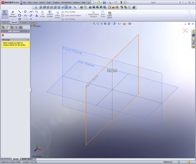


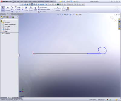
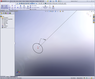
  2. Draw a horizontal straight line about 2” long (start at the origin)
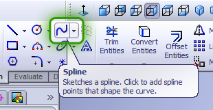
  3. Select the spline tool. Click on the end of your last line, and draw a loop.
    1. You may need to play around with this a little since you don’t want your loop to overlap itself at all
    2. We need smooth curvature, so be sure not to make any “sharp” bends


  4. Now selecting the Front plane, start a new sketch. You will need to rotate the view manually either by clicking with the center mouse wheel and dragging across the window, or by using the standard view buttons.
  5. Select the circle tool and sketch a small circle at the origin.
    1. If you created the other lines properly, this should be centered on the straight line.
  6. Dimension this circle with a 0.0625” (1/16”) diameter using the “smart dimensions” tool.


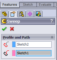
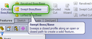
  7. Now click the Sweep/Swept feature button on the Features Toolbar.


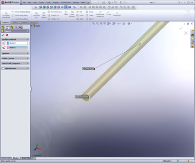
  8. Your profile is the circle; your path is the line.
    1. You might see how this could be useful for making complex paths
    2. Feel free to play with this feature when you have some free time!


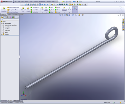
  9. If you get an error message and SW doesn’t let you create the sweep, there might be something wrong with your model.
    1. Make sure that the circle we are “sweeping” over the long profile is significantly smaller than the line. If the 3D solid will intersect itself because the loop is too small or the circle too large, SW will give you an error message
    2. There may be a sharp angle between the straight line and the loop. To fix this, simply apply a large sketch fillet to the first sketch, say, ½ to 1” radius.
  10. If you went through the yo-yo tutorial, you should now we have a yo-yo string and a body, but they’re in separate documents. We create a SolidWorks assembly document to put our pieces together.


  11. Create a new Assembly document (File, New, Assembly).
  12. Using the “Insert Components” dialog (replaces the property manager), select your yo-yo body or using the browse dialog locate and insert this.
    1. The first part you insert into an assembly will be the “origin”. If you delete this origin part and insert parts later, the assembly will NOT be constrained in 3D space, a big problem for FEA or any physical simulations.
  13. We will use the concept of mates—creating relationships between the parts using the geometry we have created.
    1. For this step we will use a less-useful mate, the “tangent” mate to fix our string to the inner radius of the yoyo.
  14. Not completely constrained, but it will work for this non-functional model (prop)
  15. Your yo-yo is complete!

Labels: , , , , , ,


Monday, November 24, 2008

Solidworks Lesson 1.3: Yo Yo

You'll notice in these lessons that I'm using SW 2008. These lessons should be valid for any version 2005+.

In this lesson I'll introduce two new features -- rotational extrusions and mirrored sketches.


Both of these tools are very useful for relating symmetrical geometry about an axis, whether 2D or 3D. If you get any errors during the lesson (highlighted lines and SW will tell you somethings wrong) try deleting some sketch relations. You can tweak the model after we're finished, but make sure you save it since we'll be working with it again later!

1. Open a new part in SolidWorks
2. Click the ‘Edit Sketch’ button (alternative way to start a sketch), and select the front plane.
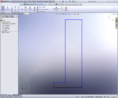
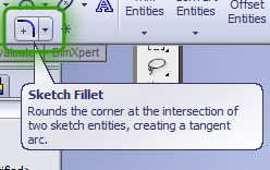
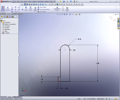
3. Draw ½ of the top of a yo-yo (1/4 of a yo-yo) shape using lines and a sketch-fillet
a. Sketch fillets work the same way as feature fillets, but are faster to calculate
b. They can make geometry changes later on more difficult, so use them wisely


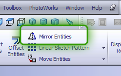
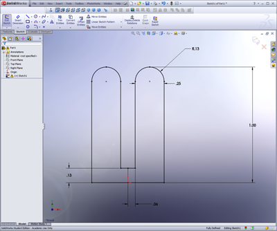
4. Add a centerline and mirror the top half of the yo-yo by selecting the entire sketch (left click and drag) and clicking the axis we want to mirror across. In this case we want to use the vertical centerline that starts at the origin (short line). This will simply reflect all of the lines we selected across that axis. You can dynamically change either side and the other side updates in real time to show the modifications. Pretty sweet!


5. Click the ‘exit sketch’ button once your sketch is fully defined
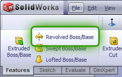
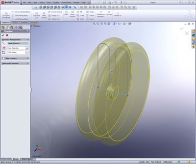
6. Click the ‘rotational extrude’ button and select the bottom line through the origin as our central axis. This is really similar to the mirror, except we are rotating a 2D sketch through space to create a 3D volume. You can do some pretty cool stuff with this tool (try making chess pieces!) so learn how to use it!.


7. Click the green check mark to create the 3d model
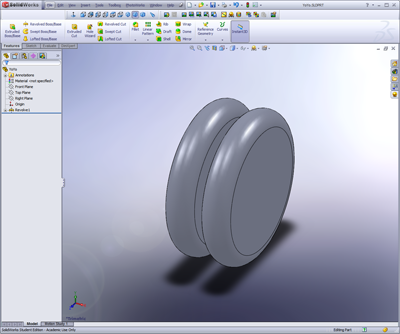
8. Play with your virtual yo-yo!


9. We can go back into our feature by right clicking on that feature in the Property Manager and selecting Edit Feature or Edit Sketch, depending on what we want to do.
10. Let’s select Edit Feature, and change the angle from 360 to 180 or 123 or 25.
11. Change your model back to 360, and click okay, or just click the red X.
12. Now let’s try Edit Sketch. This will allow us to go back and change our geometry.
a. Since we used a mirror, we only have to update one quarter of the geometry for everything to work. What a time saver!
b. You can drag the geometry around a little, or enter new dimensions.
c. Once you are satisfied with the changes, click the green check mark.

Labels: , , , ,


Subscribe to RSS Feed
Subscribe to DanShope.com
Who writes This Stuff?
Daniel Shope is the site owner and moderator of DanShope.com, a portal dedicated to robotics and engineering. Dan is currently a student at Carnegie Mellon University and is pursuing dual degrees in Mechanical and Biomedical engineering.

View Daniel Shope's profile on LinkedIn
Advertisements